Automated non-destructive quality assurance
EBNER.blog | Rainer Edtmeier, HPI, Austria
Automated non-destructive quality assurance.
HPI supplies a variety of solutions for non-destructive material testing.
The constant increase of the safety requirements for aircraft also leads to the continuous improvement of quality control. These notably expensive controls can be both sped up and fully documented by using automated testing procedures.
In particular, non-destructive methods of material testing can be used. Among these methods is conductivity testing, currently employed by our customer KUMZ, for which a system was successfully handed over at the end of November, 2019.
Conductivity testing
Conductivity is a physical measure reflecting the ability of a material to conduct electric current. Conductivity is the constant of proportionality between the density of the current and the strength of the electrical field. In a formula, it is usually represented by the Greek letter sigma (σ). The value itself is usually given in a derived SI unit, siemens per meter (S/m) – e.g. A/(Vm). As aluminum alloys exhibit very high conductivity, values are given in MS/m in all typical applications. When providing values, another possibility is to use the international copper standard. In this case, a value is given as a percentage of the conductivity of pure annealed copper. For this reason it is referred to as percent of International Annealed Copper Standard, abbreviated %IACS.
When measuring conductivity using eddy currents, fluctuating magnetic field is created using a coil. This induces a voltage in the material to be tested. Depending on the specific conductivity of the material, eddy currents develop in the material that in turn generate a second magnetic field. In accordance with Lenz’s law, this magnetic field opposes the first field and and is measured with a second coil. The amplitude and phase of the signal that is received are important when assessing the conductivity. Due to the “skin effect”, the eddy currents are more dense in layers near the surface; the higher the frequency of the magnetic field, the less it penetrates into the material.
To use an eddy current testing method is to use a fast, comparative method. That is, a reference standard is compared to the tested material to, for example, determine the success of heat treatment, the microstructure, or alloy composition.
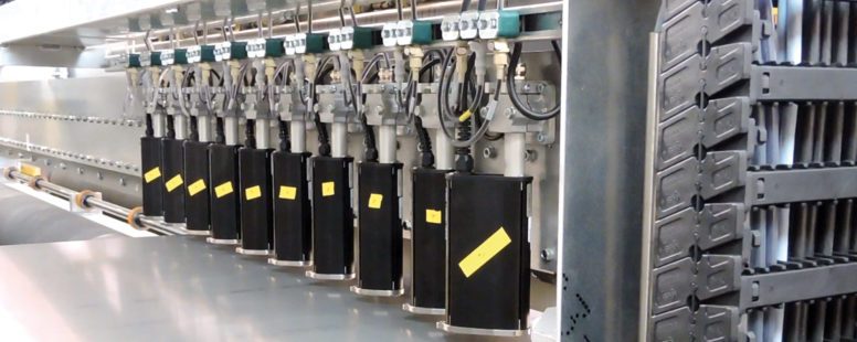
A roller table moves an aluminum slab through a fixed measuring unit, in which the specific conductivity is measured by oscillating probes positioned above and below the plate.
The sampling programs can be pre-defined for each plate, and are based on internationally recognized standards such as ASTME 1004-02, MIL STD-1537C, EN2004-1 and AMS 2772F, as well as on the customer-specific testing regulations encountered in the aerospace industry.
When used in the laboratory, it is relatively simple to control physical influencing factors such as the lift-off effect, edge effect and the temperature during measurement. In industrial applications under harsh conditions, this can be an extremely challenging task.

Geometric measurement
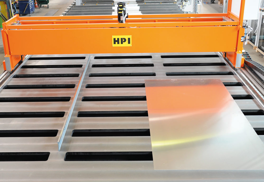
The contact-free measurement of plates is carried out using laser triangulation on a precisely-aligned measuring table 35 meters in length. The high-speed control system collects and processes data as a measuring frame travels over the plate. Along with the length and width, the flatness and squareness can be determined and displayed to the operators at the operator interface. Mechanical measuring probes also determine the plate thickness, depending on the temperature, at different freely-selected positions.

Plate marking
Following conductivity measurement, plates pass through a marking station. Here, ink jet heads mark the upper surface of the plates in accordance with either of the marking variants described in the ASTM B-666 and ASTM B-666 M-01 standards. For plate widths up to 2000 mm, the desired text is printed in lines spaced up to 150 mm apart. Plates with widths over 2000 mm are printed with two lines along their circumference.
A needle printing station is installed at the end of the facility which, depending on the thickness of the plate, scribes the upper or front sides with a pre-selected text. Depending on the specifications, this text can be generated from a combination of the plate ID number, date or other characteristics.

Data processing and documentation
All required basic data such as the unique plate ID number and the testing specifications that must be observed are sent to the facility by the higher level Manufacturing Execution System (MES, level 3). In return, all information starting with the measurement and calibration data and continuing on up to the marking options for the ink jet and needle printers is displayed at the operating station, saved, and transmitted to the level 3 system. This ensures full documentation of the testing procedure.


